PIC18F4550: Blink led with 20MHZ oscillator - XC8

PIC18F4550 Tutorial: Blink led with 20MHZ Oscillator (XC8 Compiler)
In this tutorial we are going to blink few simple led's with PIC18F microcontroller, using an external 20MHz crystal oscillator and the '__Delay' function of XC8 Compiler. Most of my previous tutorials here dealt with internal oscillator of PIC18F4550, where mostly the delays were generated with simple “for” loops. However those who wish to directly use the default __delay_us or __delay_ms function, it becomes an instant pain as the __delay function no longer accepts the variable value, like the C18 Compiler.
This tutorial is made on few requests and queries I recently received through mails, regarding the delay problems in xc8 compiler, which is: The value of the delay for the function __delay_ms() must be a constant ! For example: __delay_ms(20), (20 milliseconds delay),You cannot define a variable inside the __delay_us(), “example __delay_ms(X), where X is a int variable”, this was possible with C18. There is a solution to the delay problem with XC8 Compiler.
Hence I decided to put it together as tutorial to blink a simple led using external 20 MHZ Crystal oscillator on pic18f4550 with XC8 compiler and Mplab x ide.
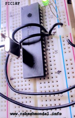
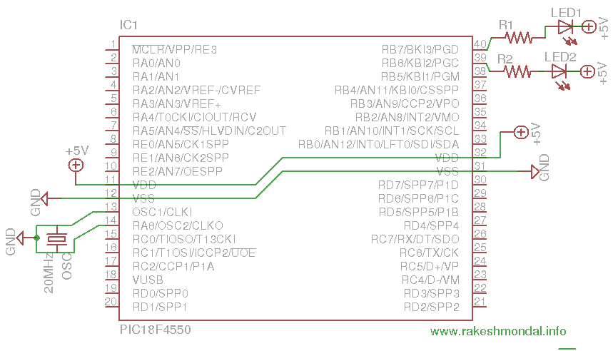
It is all about setting the compiler directives correct to get the external oscillator working fine. The 20 MHz crystal oscillator is interfaced with two 22p capacitor as explained in the oscillator section in the pic18f4550 datasheet. Please download the latest version of datasheet for PIC18F4550 from the microchip website. A 0.1u cap is also added close to microcontroller.
The basic logic with any microcontroller is to turn the led on and then turn off by setting the registers, with some good delay in between the on and off, enough to catch the effect by human eye. There are many ways to generate such delays, such as using delays.h, making your own delay “for” loops,timer etc.
The theory goes as, if you wish to use xc8 delay function then you have to include delays.h as a header (preprocessor) and then include __delay_us(); or __delay_ms(); (with double underscore) anywhere you wish to have a delay. The desired delay must be a constant, such as ” __delay_ms(500);” which theoretically sounds simple.
But the problem is with the limits to the constant which is defined inside the __delay_ms() function. For example if you wish to generate a 200ms delay, then according to the theory all you have to do is :- __delay_ms(200) and you are done, but compiler wont accept the value and would result in an error. This is due to the limitation with the value of the constant.
The limit of the constant defined inside the delay function depends on the XTAL value defined in the Compiler directives.
"#define _XTAL_FREQ 20000000UL"
This limitation of the constant and the issue with passing a variable value to the Delay function can be solved by creating a function prototype, or by calling the delay function with a "for loop" whose parameters can be a variable. Now with the limited range of constant you can create delays of any length.
For example, if were to generate a delay of 200ms without any error, then i would enclose the __delay_ms(20); inside a "for" loop and call it 10 times, which should result a 200 millisecond delay.
The code I wrote below generates a delay of approximately 200ms, where for 20 MHz I have defined _XTAL_FREQ 20000000UL. Please note that XTAL_FREQ doesn’t really sets the frequency of the hardware, but it’s still required for __delay_ms to work. If you directly write the milliseconds values as __delay_ms(200); then immediately the compiler would throw an error on compiling the code. For the configuration I defined in my code,the compiler doesn’t want to accept the ms value greater than 39 milliseconds. Hence creating “for” loop again can be helpful when the ms value can’t be more then 39 for _XTAL_FREQ 20000000UL.
For example:
for ( int x=0; x<=20; x++ )
{
__delay_ms(10);
}
Approximately creates a delay of 200ms.
Schematic
Let's Start with Coding
-Start MPLABX IDE and create a New Project as explained in the previous post for pic18f4550.
-Add a new file and save it as MAIN.C
-Then start typing the source code as below.
Source Code:
#include <p18f4550.h>
#include <delays.h>
#define LD1 LATBbits.LATB7
#define LD2 LATBbits.LATB6
#define _XTAL_FREQ 20000000UL // This one is just for __delay_ms
#pragma config PLLDIV = 5 // PLL Prescaler Selection bits (Divide by 5 (20 MHz oscillator input))
#pragma config CPUDIV = OSC2_PLL3 // System Clock Postscaler Selection bits ([Primary Oscillator Src: /2][96 MHz PLL Src: /3])
#pragma config USBDIV = 2
#pragma config FOSC = HSPLL_HS // Oscillator Selection bits (HS oscillator, PLL enabled (HSPLL))
// Everything is Off After this to make sure things do not go wrong
#pragma config FCMEN = OFF // Fail-Safe Clock Monitor Enable bit (Fail-Safe Clock Monitor disabled)
#pragma config IESO = OFF // Internal/External Oscillator Switchover bit (Oscillator Switchover mode disabled)
#pragma config PWRT = OFF // Power-up Timer Enable bit (PWRT disabled)
#pragma config BOR = OFF // Brown-out Reset Enable bits (Brown-out Reset disabled in hardware and software)
#pragma config BORV = 3 // Brown-out Reset Voltage bits (Minimum setting)
#pragma config VREGEN = OFF // USB Voltage Regulator Enable bit (USB voltage regulator disabled)
#pragma config WDT = OFF // Watchdog Timer Enable bit (WDT disabled (control is placed on the SWDTEN bit))
#pragma config WDTPS = 32768 // Watchdog Timer Postscale Select bits (1:32768)
#pragma config CCP2MX = OFF // CCP2 MUX bit (CCP2 input/output is multiplexed with RB3)
#pragma config PBADEN = OFF // PORTB A/D Enable bit (PORTB<4:0> pins are configured as digital I/O on Reset)
#pragma config LPT1OSC = OFF // Low-Power Timer 1 Oscillator Enable bit (Timer1 configured for higher power operation)
#pragma config MCLRE = OFF // MCLR Pin Enable bit (RE3 input pin enabled; MCLR pin disabled)
#pragma config STVREN = OFF // Stack Full/Underflow Reset Enable bit (Stack full/underflow will not cause Reset)
#pragma config LVP = OFF // Single-Supply ICSP Enable bit (Single-Supply ICSP disabled)
#pragma config ICPRT = OFF // Dedicated In-Circuit Debug/Programming Port (ICPORT) Enable bit (ICPORT disabled)
#pragma config XINST = OFF // Extended Instruction Set Enable bit (Instruction set extension and Indexed Addressing mode disabled
#pragma config CP0 = OFF // Code Protection bit (Block 0 (000800-001FFFh) is not code-protected)
#pragma config CP1 = OFF // Code Protection bit (Block 1 (002000-003FFFh) is not code-protected)
#pragma config CP2 = OFF // Code Protection bit (Block 2 (004000-005FFFh) is not code-protected)
#pragma config CP3 = OFF // Code Protection bit (Block 3 (006000-007FFFh) is not code-protected)
#pragma config CPB = OFF // Boot Block Code Protection bit (Boot block (000000-0007FFh) is not code-protected)
#pragma config CPD = OFF // Data EEPROM Code Protection bit (Data EEPROM is not code-protected)
#pragma config WRT0 = OFF // Write Protection bit (Block 0 (000800-001FFFh) is not write-protected)
#pragma config WRT1 = OFF // Write Protection bit (Block 1 (002000-003FFFh) is not write-protected)
#pragma config WRT2 = OFF // Write Protection bit (Block 2 (004000-005FFFh) is not write-protected)
// Write Protection bit (Block 3 (006000-007FFFh) is not write-protected)
#pragma config WRTC = OFF // Configuration Register Write Protection bit
#pragma config WRTB = OFF // Boot Block Write Protection bit (Boot block (000000-0007FFh) is not write-protected)
// Data EEPROM Write Protection bit (Data EEPROM is not write-protected)
#pragma config EBTR0 = OFF // Table Read Protection bit
#pragma config EBTR1 = OFF // Table Read Protection bit
#pragma config EBTR2 = OFF // Table Read Protection bit
#pragma config EBTR3 = OFF // Table Read Protection bit
#pragma config EBTRB = OFF // Boot Block Table Read Protection bit
void main(void)
{
TRISBbits.TRISB6 = 0; // Setting output
TRISBbits.TRISB7 = 0; // Output
while(1)
{
LD1=1;
LD2=0;
for ( int x=0; x<=10; x++ )
{
__delay_ms(20); // 20x10 200ms
}
LD1=0;
LD2=1;
for ( int x=0; x<=10; x++ )
{
__delay_ms(20);
}
}
}
/* THE END */
Download the code main.c
NEXT CHAPTER4: Tutorial 2 – Method 2- Blinking led with pic18f4550 – header files
Thanks for Reading
Ron


