USB Interface Board Tutorial Using PIC18F4550

USB Interface Development Board Tutorial -1
STAGE/PART-1
MAKING OF THE MAIN CIRCUIT BOARD
CONTROL YOUR DEVICES FROM COMPUTER USING USB PORT – pic18f4550 + MPLAB IDE
INTRODUCTION ( USB PROJECT) : STEP 1
This project demonstrates a computer control interface using a USB Board. (USB INTERFACE PROJECT). This tutorial will show you a simple way to control some device like led, motors and other devices with computer through a USB Board. The traditional way to control devices from a computer was to use a parallel printer port which is much more easy to implement than that of a USB PROJECT, but the only limitation with parallel printer port is that the latest computer does not comes with parallel printer port. So you can use this project as an alternative to a parallel port interface. pic18f4550 usb interface project is Human Interface Device (HID).
If you are thinking that Buying a USB to Parallel port converter would work then you are wrong ! , hence this one is an very good alternative .
For this USB Interface Board we are going to use a Microcontroller “PIC18F4550”
This tutorial is not so difficult for a experienced person however I am also posting a step by step procedure for beginners . If you are an experienced person with microcontroller then all you need to do is to make the USB board Circuit and then burn the firmware into the microcontroller , with a microcontroller programmer and then install the drivers on your system , and finally launch the application after connecting the main board to the computer with a USB PORT.
-Experienced personal can go to end of Interface Board link and can download everything at the end of that page. Beginners can follow this page and continue on for full description.
- This project allows you to control some device with your computer on clicks of few buttons on a small application written in C# which communicates through the pic18f4550 microcontroller. But creating this board can be difficult for beginners and easy for experienced persons.
SO beginners please follow this entire tutorial step by step.
Please watch the video below so see the PIC18F4550 Microcontroller in action.
APPLICATION OF USB DEMO BOARD (USB ROBOT)
In traditional parallel printer port interface project all you have to do is to connect few led’s across you parallel port (printer port) and code an application in Visual Basic or C# and you are done. But when it comes to USB port control, its quiet complex way than parallel printer port control.
This Tutorial will show you in details for constructing this USB pic18f4550 circuit and running it from a C# application. Please read and follow all the posts.
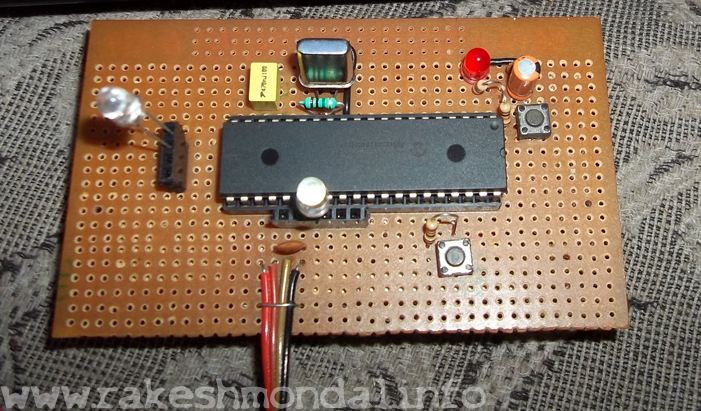
PIC18F4550 USB Interface Development Board

PIC18F4550 Interface Board
I found a kind of tutorial on microchip.com to control one led with PIC18F4550, and from there I started to do experiments on source codes and then I came up with controlling 8 led’s. For now I am showing only 6 LED controls.
This USB Interface board pic18f4550 is programmed to control 6 led’s and it can be manipulated easily to control 8 led’s. In spite of led’s you can interface it to some other electronics components to control, like DC motor or stepper motor or can make your own robotics application as I did. A small software coded in C# can control the glowing of led’s with clicks of mouse or by pressing some keys.
Let's First Take care care of circuit board then we will come back to MPLAB IDE to program it.
Let’s start with making the circuit board first, then we will discuss about other coming steps for making this demo interface development board like firmware, Driver, bootloading, writing our own code using MPLAB IDE, etc. Please read all my steps carefully and follow them properly, in first reading it may not be so much clear, so I suggest giving a second reading. As you go further, it will start to get clear slowly. I am trying to make it as easy as possible for better understanding.
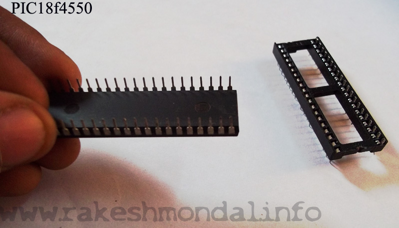
-For my project I bought this PIC18f4550 microcontroller for Rs. 375 (Indian currency) that is around 6.5 $. It is available in any electronics shop.
The schematic provided in this tutorial is a snapshot picture from EAGLE Layout designer.
So get all the components in the list i have provided below and heat up your soldering iron and lets begin. Be careful while working with soldering iron.
pic18f4550 USB Board SCHEMATIC
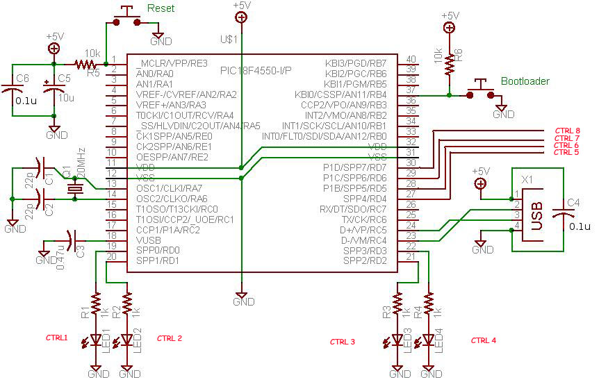
SCHEMATIC
TIP: Save the schematic and pin diagram for this USB demo interface Board. Refer the pin diagram time to time while soldering to avoid confusion. It is better to do labeling in the PCB to avoid confusion while you are soldering.
Components Required for USB Interface Board
| Label | Value | Quantity |
| C1 | 22p | 1 |
| C2 | 22p | 1 |
| C3 | 0.47u | 1 |
| C4 | 0.01u | 1 |
| C5 | 10u | 1 |
| C6 | 0.01u | 1 |
| Q1 | 20MHZ | 1 |
| MP | PIC18F4550 | 1 |
| R1,2,3,4 | 1K | 1 Each |
| R5,6 | 10K | 1 |
| Push switch | 2 Pins | 2 |
| USB Socket | - | 1 |
| LEDS | - | - |
And a soldering iron of course
PIN DIAGRAM - PIC18F4550
Guidelines While Making the Circuit Board for USB Interface
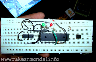
It is recommended to use a PCB for making this USB Interface Board . Over breadboard there are always chances of loose connections. On a Breadboard Sometime all the connections are perfect but still the PIC18F4550 is not detected by the system, (it will freak you out) , so better way is to use a PCB, I myself faced this problem, even though all the circuitry and connections were perfect and all checked up several times, but still no sign of life. So better to use a PCB on the first shot. You can alter the connection anytime on PCB if any mistake is detected on the USB interface board you are making.
-There are some basic things that you must always be cautious about while experimenting with any microcontroller. One thing that you must always be cautious about is, “the voltage”.
-In PIC18F4550 data sheet you can find the Vmax value, i.e. 5v. The voltage input to the microcontroller must never exceed this value under any condition or it will burn the microcontroller for sure.
The input voltage to a pic18f4550 Microcontroller under any condition should never exceed 5 V.
Always refer the data sheet of the respective microcontroller before doing anything with it.
-The standard voltage in any standard USB port is 5V, so you don’t have to worry about Vmax voltage while connecting this PIC18F4550 microcontroller Board to your computer USB port. For our USB Interface Board you don't need any External Power supply. If just in case you have to use an external power supply in spite of USB power supply then you can use a IC 7805 voltage regulator to keep the input voltage at constant 5 v.
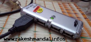
The maximum length of any USB cable is 5 meters to the max. But I suggest for initial steps keep the connecting USB wire less than a meter for our board to work perfectly. There are only 4 or 5 pins in a USB PORT. D+ , D– , -Ve voltage (GND), +5v voltage and shield wire. You can check out for USB COLOR code pinout diagram in Google. Save a copy of USB PORT pinout config Picture from Google for further reference while you go on.
USB INTERFACE BOARD PIC18F4550


-The crystal oscillator used in this pic18f4550 USB Interface Interface Board is 20MHZ crystal oscillator which is used for internal oscillation of the microcontroller and it is connected on 13 and 14 pin. I suggest to add a 1M resistor (1M=1000k) before the crystal oscillator on 13 and 14 pin.
- Don’t forget to short 11th and 32nd pin together and to 5 v of the USB +5v (+ve voltage) , similarly 12th and 31st pin to GND.(-ve voltage).
-The led’s on SPP 0 to SPP 7, add a 1 k resistance to each LED's. In case if you want to know how to identify the LED pins you can refer my LED IDENTIFY post.
-There are two switches in our board, one for bootloading and another one is the reset button, I will explain about the bootloading routine later in my other posts in details.
-By this USB Interface board we are going to control six pins, from SPP 0 to SPP7. For now we will use these pins to glow led’s , but these are control pins, we can use these to control other things too. It can easily interfaced with L293D Motor Driver, or you can interface it to run other dvice over USB like DC Motor, Stepper Motor, relay switches , servo etc. etc.
After you are done making with the USB Circuit Board
Simply connecting the USB cable from your computer to the USB Interface Board immediately after you complete the soldering won’t make it start working right away. Before the system (your computer) can detect this new hardware , you need to load a microcontroller program (code , usually a small hex file) into the pic18f4550 microcontroller, then your computer will detect it like any new external plug and play hardware and then you can install the driver‘s in your computer for this Board. A Step by Step tutorial to install the driver and links to download the drivers are given in my coming posts.
-The source Code for this pic18f4550 microcontroller is written in an IDE named as MPLAB IDE with a Compiler.
-The compiled code for this microcontroller will generate the output in the form of a small hex file. That hex file (firmware) will be loaded into the pic18f4550 microcontroller.
-For loading this Hex code into the pic18f4550 microcontroller you will need a special hardware [Microcontroller Programmer] I will also provide a tutorial to make your own Microcontroller Programmer to load the code into the Pic18f4550 Microcontroller. I will get into more details in my coming posts.
Usually the program loaded into the EPROM of the microcontroller is the firmware. The Firmware is loaded into the EPROM of the microcontroller, then we have to connect it to the USB port of the computer and then it will detected and then we have to provide the driver.
-After the circuit design is complete its time to test it out, as said before if you directly connect the USB Interface Board to your computer then the board will show no activity, we have to load it with a firmware first !!
So lets carry on with the next step - "1st time programming of the microcontroller" .
STEP 2 >>> 1st time programming of the microcontroller

PIC18F4550 CHIP
Thanks for reading
Rakesh Mondal
ron