L293D Motor Driver IC

L293D Description
L293D is a typical Motor driver or Motor Driver IC which allows DC motor to drive on either direction. L293D is a 16-pin IC which can control a set of two DC motors simultaneously in any direction. It means that you can control two DC motor with a single L293D IC. Dual H-bridge Motor Driver integrated circuit (IC).
The l293d can drive small and quiet big motors as well, check the Voltage Specification at the end of this page for more info.
You can Buy L293D IC in any electronic shop very easily and it costs around 70 Rupees (INR) or around 1 $ Dollar (approx Cost) or even lesser cost. You can find the necessary pin diagram, working, a circuit diagram, Logic description and Project as you read through.
Concept
It works on the concept of H-bridge. H-bridge is a circuit which allows the voltage to be flown in either direction. As you know voltage need to change its direction for being able to rotate the motor in clockwise or anticlockwise direction, Hence H-bridge IC are ideal for driving a DC motor.
In a single L293D chip there are two h-Bridge circuit inside the IC which can rotate two dc motor independently. Due its size it is very much used in robotic application for controlling DC motors. Given below is the pin diagram of a L293D motor controller.
There are two Enable pins on l293d. Pin 1 and pin 9, for being able to drive the motor, the pin 1 and 9 need to be high. For driving the motor with left H-bridge you need to enable pin 1 to high. And for right H-Bridge you need to make the pin 9 to high. If anyone of the either pin1 or pin9 goes low then the motor in the corresponding section will suspend working. It’s like a switch.
TIP: you can simply connect the pin16 VCC (5v) to pin 1 and pin 9 to make them high.
L293D Pin Diagram

Working of L293D
There are 4 input pins for l293d, pin 2,7 on the left and pin 15 ,10 on the right as shown on the pin diagram. Left input pins will regulate the rotation of motor connected across left side and right input for motor on the right hand side. The motors are rotated on the basis of the inputs provided across the input pins as LOGIC 0 or LOGIC 1.
In simple you need to provide Logic 0 or 1 across the input pins for rotating the motor.
L293D Logic Table.
Lets consider a Motor connected on left side output pins (pin 3,6). For rotating the motor in clockwise direction the input pins has to be provided with Logic 1 and Logic 0.
• Pin 2 = Logic 1 and Pin 7 = Logic 0 | Clockwise Direction
• Pin 2 = Logic 0 and Pin 7 = Logic 1 | Anticlockwise Direction
• Pin 2 = Logic 0 and Pin 7 = Logic 0 | Idle [No rotation] [Hi-Impedance state]
• Pin 2 = Logic 1 and Pin 7 = Logic 1 | Idle [No rotation]
In a very similar way the motor can also operate across input pin 15,10 for motor on the right hand side.
Circuit Diagram For l293d motor driver IC controller.
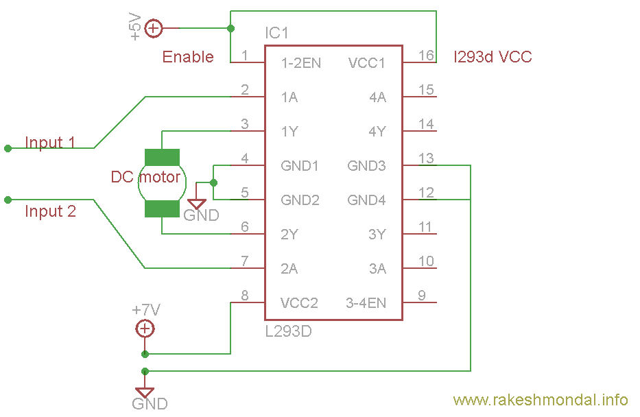
Download the l293d Schematic in as Eagle Project
Voltage Specification
VCC is the voltage that it needs for its own internal operation 5v; L293D will not use this voltage for driving the motor. For driving the motors it has a separate provision to provide motor supply VSS (V supply). L293d will use this to drive the motor. It means if you want to operate a motor at 9V then you need to provide a Supply of 9V across VSS Motor supply.
The maximum voltage for VSS motor supply is 36V. It can supply a max current of 600mA per channel.Since it can drive motors Up to 36v hence you can drive pretty big motors with this l293d.
VCC pin 16 is the voltage for its own internal Operation. The maximum voltage ranges from 5v and upto 36v.
TIP: Don’t Exceed the Vmax Voltage of 36 volts or it will cause damage.
A sample Project
A sample project demonstrating the operation of L293D motor Driver IC with PIC18F4550 USB demo interface board. The Control signals are being passed to the Driver with this board.
L293D Motor Driver Interface with PIC18F4550 USB Interface Board


Thanks for reading
Rakesh Mondal
ron