C# Software and Firmware, USB INTERFACE BOARD
C# Software and Firmware-USB INTERFACE BOARD
    C# Software Application for PIC18F4550
(DOWNLOAD PAGE)
Author: Rakesh Mondal
C# Software Application and Firmware for PIC18F4550 Board
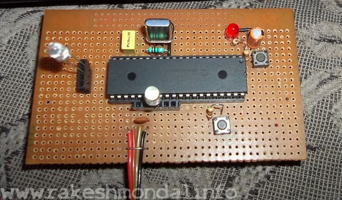
To continue further with this project you would need to download my version of Firmware to control 6 LED’s and a Software application which is written in C# sharp, a project file has been also enclosed with the download files given below. Download the software, firmware and the drivers for this board according to your operating system. Upload the firmware with your programmer and connect the board to the computer and install drivers manually. The board has been tested many times successfully with windows XP, Vista and Windows 7, however it has never been tested on win 8.
DOWNLOAD- Firmware for PIC18F4550 to control 6 LEDS
- FIRMWARE -CONTROL firmware for 6 LEDS(DOWNLOAD)
- Software - C# Software application Download (DOWNLOAD)
- Driver - XP and WIN7
This version of firmware will allow you to control 6 leds from a USB demo Interface board.
Now connect 8 LED’s across CTRL 1, 2,3,4,5,6,7,8 (RD 0 to RD 7) with a 1k resistance each.
Schematic
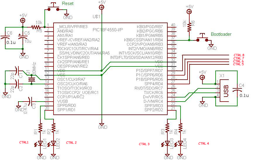
Out of all the 8 LEDs, you should be able to control 6 LED’s with the sample C sharp application provided in the starting of this page.
The configuration of the PORT D pins on PIC18F4550 are set in a way that the C sharp application should be able to glow the LED’s connected across RD 0, RD 1, RD 2, RD 3, RD 6 and RD 7. However RD 5 and RD 6 are used for indication purpose only to see if the Board is live and USB Communication exists. When the USB Interface Board is live and ready, the LED connected across RD 5 and RD 6 would blink alternatively with short delays in-between. This also indicates that the board is Read Only Mode.
If the LED connected across RD0 and RB1 is blinking alternatively then it indicates that the microcontroller board is in READ/WRITE mode (Boot load mode). In the Boot loading load there would be no control on the rest of LED’s.Only when the USB Interface board is in Read mode, only then it is possible to control the LED’s clicking the LED.
Software Application to control USB interface board

After successful connection with PC computer, initializing the C# software and hit the Check status button on the Application to confirm if the board is communicating with the computer. On successful connection with the Board the software would show you the VID in the status box. If not then check the connection and restart the Software.
The application software is written in C# (c-sharp) using visual studio 2010, the bugs reported by the users in the older version of application were fixed in the latest version of the application [updated Jan 2014]
While working with the board if due to any disturbance in the USB connection if the connection to the board is lost but the status LED (RD 5 and RD6) is still blinking alternatively then you need to restart the software again.
END OF USB DEMO INTERFACE BOARD PROJECT
With this Simple USB interface board you can make your own applications the way you want it. I have also posted some of the application of this USB interface board such as , DC motor Controller and USB Stepper motor Controller. This USB interface board just serves a media to connect through USB connection, use the way your imagination drives you.
Here are some example applications of the USB interface Board.
Thanks for reading
Rakesh
Ron
Related Topics
USB Interface Board using PIC18F4550
PIC18F4550 Programming- Blinking LED
IR Sensor Circuit interface PIC18F4550
USB Stepper Motor Driver
Stepper Motor interface PIC18F4550