BOOTLOAD THE PIC18F4550 – FIRMWARE UPDATING
BOOTLOAD PIC18F4550 – FIRMWARE UPDATING
SETTING THE PIC18F4550 IN RD/WR ( BOOTLOAD ) MODE FOR BOOTLOADING
Loading / updating new code into the USB INTERFACE BOARD can be done with a Bootloader Software. While searching for good bootloader, I found some nice tutorial on eegeek.net and piccoder.co.uk for BOOTLOADING the USB INTERFACE board.
The tutorial posted on eegeek.net and piccoder.co.uk are very nice for initial understanding of USB INTERFACE BOARD. The firmware posted on piccoder.co.uk and eegeek.net was programmed to control only two leds , ( led 3 and led4 in the pic below) for demonstration of this USB Interface.
The firmware that is posted in the next tutorial will enable/ allow you to control 6 leds ( connected across CTRL1 , CTRL 2 ,CTRL 3 , CTRL 4 , CTRL 7 ,CTRL 8 – refer schematic below , CTRL 5, and CTRL 6 will flash alternatively)
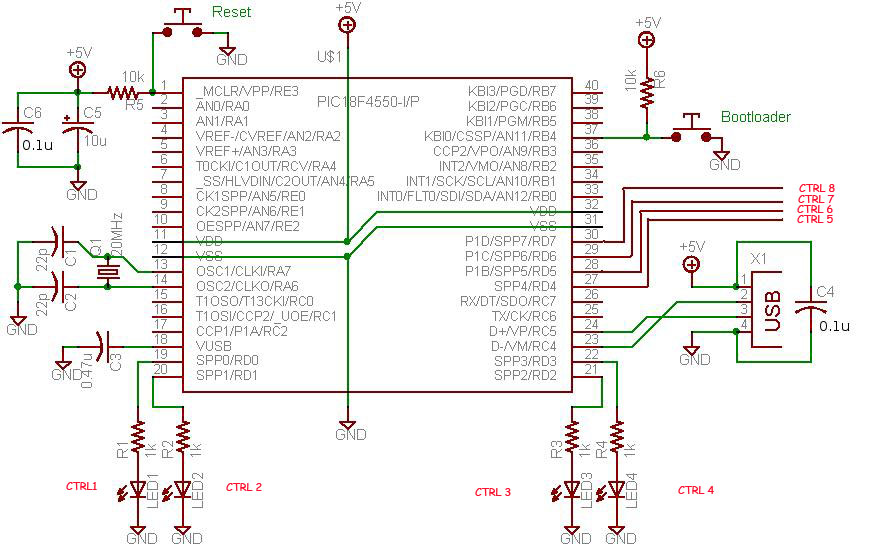
PIC18F4550 DEMO SCHEMATIC
Piccoder.co.uk and eegeek.net have their own version of Bootloader software. My personal favorite version of BOOTLOADING Software is from eegeek.net , you can download the entire project file of his version of BOOTLOADING software from his website.
The downloaded zip file from eegeek.net will contain entire project file of the USB board, like mplab project, c# application , a BOOTLOADING software in C# and a firmware to control two leds . Search for BOOTLOAD folder inside the zip file and run the bootloading software inside the DEBUG folder (coded in C#).
STEPS OF BOOTLOADING
For loading new code into the USB BOARD it is necessary that the USB BOARD must be set to Bootload mode. There are two modes of a operation, READ mode (you will be able to control this Board only when the board is in READ MODE)and READ/WRITE mode (BOOTLOAD mode).
Connect the USB DEMO BOARD to your P.C , and start the BOOTLOADER Software. Import the new hex file that you need to write, into the BOOTLOADING software. [I will provide the new Firmware in my next post]
It is possible to write new code into the EPROM of PIC18F4550 only when it is in RD/WR mode.
VIEW this video below to learn how to set the PIC18F4550 USB demo Board in BOOTLOAD MODE.
On the USB INTERFACE BOARD gets initialized press the RESET button (keep it pressed) and then hit the BOOTLOAD button once. Then the USB INTERFACE BOARD goes to BOOTLOAD mode.
Now you can notice the software status PIC DETECTED In read/ write Mode , BOOTLOAD MODE. Import the firmware code ,Click on the write button. The firmware imported in the boot loader software , will be loaded into the microcontroller. You can then verify the code by clicking the READ button the BOOTLOADING software.
NOTE: There is a erase button, DO NOT CLICK ON THE ERASE button, or it will clean the previously written firmware and you have to use the JDM again.
Now please go to my next post for downloading the firmware that will enable to control these 6 leds from your computer.
NEXT STEP >> Firmware to control 6 LEDS using PIC18F4550