USB Interface Board Driver Installation PIC18F4550
USB Interface Board Driver Installation
Connecting PIC18F4550 First Time
How to Install Driver to PIC18F4550 first time
(Installation of USB PIC18F4550 Driver ) CONFIGURATION
This tutorial will try to explain how to make your interface development board to work for the first time. Without a Demo hex code inside PIC18F4550's flash memory, it won’t respond even if we connect the Demo Interface Board Directly to computer. In my previous post we have successfully loaded the Demo Hex Code into the PIC18F4550 using a Serial JDM programmer, so now lets continue with further steps. For continuing further step of Driver Installation and BOOTLOADING operation you need to download and Install USB MICROCHIP FRAMEWORK from microchip website. The framework contains various resources, sample firmware and various Docs that can help you further learning in PIC microcontrollers. The framework that I have used is version 1.2v . You can download this framework directly from microchip website. There are other versions of the Microchip stack also. You can install the version you like or you can also proceed with this v1.2 .
Microchips USB framework MCHPFSUSB v 1.2
Or you can Download the Dirvers Directly from here. If you want just the drivers.
- Windows XP USB Interface Driver
- Windows Vista/Windows 7 Driver
This framework has also many other versions, it contains various software, samples, examples and demo firmware for learning and practicing. Microchip keeps on updating this framework time to time by releasing new version. The firmware provides nice Resources for make learning more easy.
All the packages and resources after Installation of framework will be installed by default in the C:\ MCHPFSUSB folder .
PIC18F4550 DRIVER INSTALLATION
Now lets get back to our main topic. After the demo code is inserted into the PIC18F4550 first time with a JDM as mentioned here , the next step is to chip off the PIC18F455O from the JDM (after 1st time loading of HEX code) and insert the PIC18F4550 microchip back into the USB INTERFACE BOARD.
Connect the USB INTERAFEC BOARD usb cable to the USB port of your computer. At first Attempt the USB DEMO BOARD wont show any activity ( neither the leds will start to flash nor windows will ask for drivers) .
For starting the Board, You need to initialize it in BOOTLOAD MODE. In the USB Board there are two buttons,one is the RESET BUTTON and another is the BOOTLOAD button.
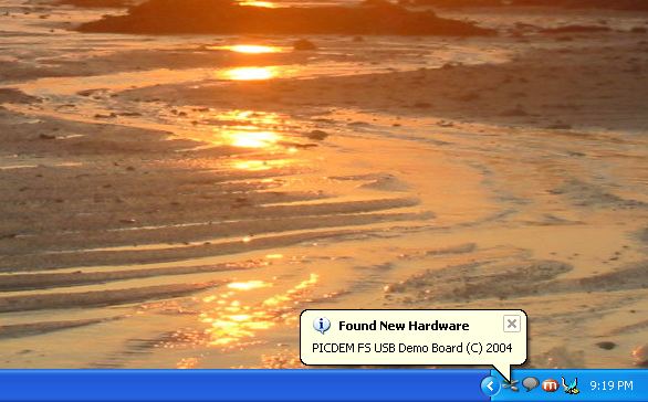
HOLD the RESET BUTTON (keep it pressed) and then hit the BOOTLOAD button (once) and then release both buttons. The window will then detect the PICISF4550 USB hardware and ask for Drivers for this PIC18F4550 board.
If the windows is not asking for drivers then there might be some problem with USB INTERFACE BOARD. Check if the soldering is done properly. Check if the USB cables are connected properly , check if you have done any mistake with polarity of the USB cable, check it with a USB pin out diagram for possible mistakes with USB cables..
Don’t forget the step, keep the RESET button pressed then then hit the BOOTLOAD button and then release both the buttons , the windows will ask for drivers with a “Windows USB device plug Sound Notification , that usually windows gives in case of connecting any flash drives and other device)
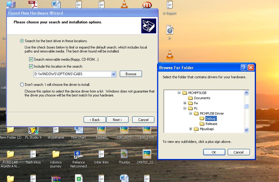
The Drivers for this USB device is located in
C:\MCHPFSUSB\Pc\MCHPUSB Driver\Debug folder.
When the windows will ask for drivers, go for manual driver search, and browse to above mention location folder for Drivers.
After the Drivers are Installed Led1 and Led 2 will start to flash alternatively .Which means that your USB device is Perfectly communicating with your PC.

After the drivers are installed you don’t have to hit RESET and BOOTLOAD button every time you connect this Development board to your p.c . As soon you as you plug the USB cable the leds (ctrl1 and ctrl2 leds) will start to flash alternatively hereon.
NOTE: Its not necessary that every time you have to use a JDM programmer for burning the firmware into the PIC18F4550, the JDM programmer is USED only for the FIRST time programming of the code, for consecutive stages you can use a BOOTLOADING SOFTWARE to burn new code directly from USB BOARD.
Now the USB DEMO INTERFACE BOARD is ready , and now we can LOAD our own firmware code into the chip Directly from USB BOARD,( without JDM).
NEXT STEP
So now lets continue >> Bootloader PIC18F4550
Thanks for reading
Rakesh Mondal
ron