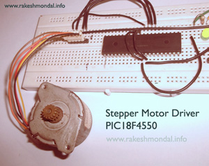
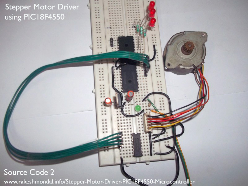
Stepper Motor Driver using PIC18F4550 Microcontroller

Stepper Motor Tutorial
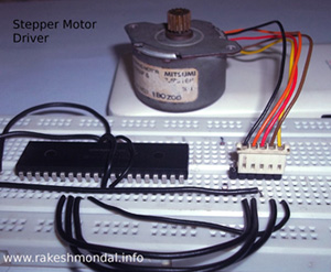
In this tutorial we are going to drive a Single unipolar stepper motor using PIC18F4550 Microcontroller in various different stepping modes. The source code and Project files are free to download at the end of this page.
Stepper motor due its excellent features is very famous in between hobbyist for various robotic applications. Running DC, Stepper motor and servo is the most basic requirement in any robotic application which moves. Stepper motor’s ability to run in various modes with various speed and torque gives it a more degree of advantage over the simple DC motor for various projects, especially in robotics based projects.
 So in this basic stepper motor tutorial we will learn to drive a simple 5 wire uni-polar stepper motor using a 40 pin PIC18F4550 microcontroller.
For a little more sophisticated Stepper motor Driver you can also follow my USB Stepper Motor Driver project which is quiet similar to current project , however this driver tutorial does not involve any interaction to any computer system directly except for writing the codes.
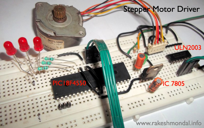
-5 wire Unipolar Stepper Motor
-Bread board
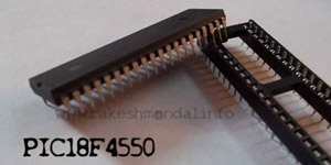
-PIC18F4550 Microcontroller
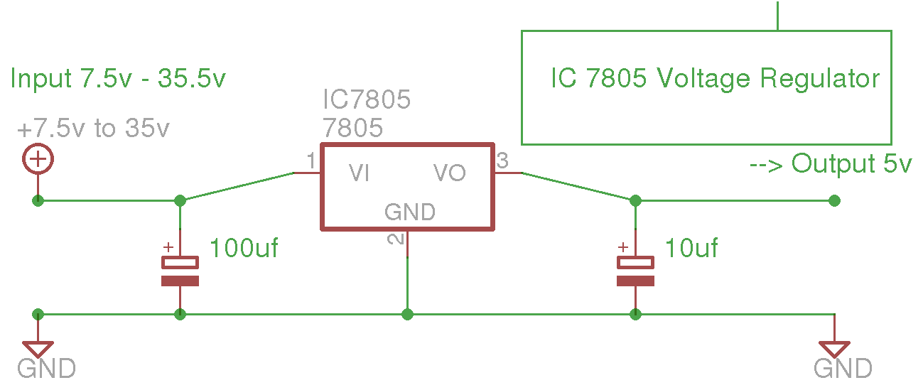
-IC 7805
-ULN2003 (For better Results)

The stepper Motor can be also connected directly without ULN2003, but during the testing the results were not satisfactory hence a ULN2003 was added.
Caution!: 9V power supply is given to Stepper Motor which is not same as the voltage for the PIC18F4550 power supply (5V). Do not connect both the power supply together as the PIC18F4550 cannot bear more than 5V, both the supply must not be shot together or the microcontroller will be damaged.
If you have a single source of power supply for both the Stepper motor supply and Microcontroller, then add a MCP102 or an IC 7805 Voltage regulator (5v) before the VSS terminal of the Microcontroller, which would keep the input voltage to microcontroller at 5V.
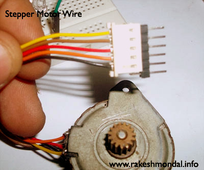
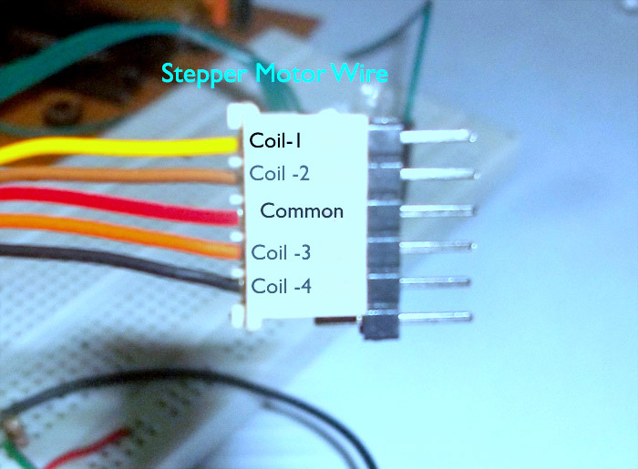
Stepper Motor Wire Color Code
Compiler IDE and Source code
The source code is compiled with MPLAB X IDE and X C8 Compiler which can be loaded into the microcontroller using pickit2 or JDM Programmer. It can be also compiled with Mplab and C18 compiler without much effort. For convenience I have added both versions of the source code at the end of this post with the compiled HEX file. For our Stepper Motor Driver we are not going to use any external Oscillator with the microcontroller.
There are two source code posted here, the source code 1 demonstrate the basic and simple Single Stepping mode of a stepper motor. The second source code is little more complex and has three other stepping modes (Single, FULL and HALF) cycling with delay of 5 seconds each.
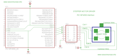
 The first code demonstrates Single stepping mode for driving our 5 wire uni-polar stepper Motor. Where the Stepper Motor coils are connected to PIC18F4550 pins, RD4, RD5, RD6 and RD7.
You would also require a header file which contains the various compiler directives, which is common for both the source codes 1 and source code 2.The delay has been set to 50000 microsecond or 50 milliseconds.
If in case if you want to use __delay_us( ); instead of __delay_ms( ); for adding delays then you can use some time converters or my favorite online scientific calculator ( eeweb calculator ) for ms to us conversion.
Download Steppemotor.c, Header.c and output1.hex
You can download the entire Mplab X –XC8 project at the end of this post.
In the above sample source code excites each coil with delay of few milliseconds and loops over again from the beginning endlessly for the next cycle.
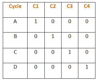
In this mode only single phase is energized at a time, and for completing one complete revolution of the motor shaft it take 4 cycles, and only one coil is energized at a time and during next cycle previous coil goes low 0 and next one goes high 1.
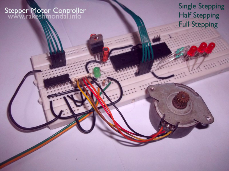
 This source code demonstrates three modes of stepper motor which are Single stepping mode, half wave stepping mode and Full Wave stepping mode. Each mode executes for 5 to 6 seconds and then executes next mode. The schematic for this Source code is little different.
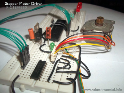
The Stepper Motor coils are connected across PIC18F4550 pins RD4, RD5, RD6 and RD7. Also 4 LEDS are connected across RB0, RB1, and RB2 acting as indicator for the mode in which the stepper motor is running. Follow Schematic 2 for Source code 2.
Stepper motor stepping modes
RB0 - Single Wave Stepping
RB1- Half Stepping mode
RB2- Full Stepping mode
Download Steppemotor.c, Header.h and output1.hex
You can download the entire Mplab X –XC8 project at the end of this post.
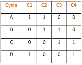
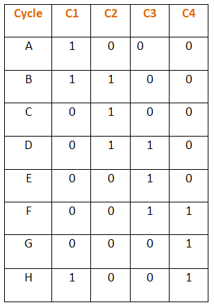
Full stepping mode and Half stepping Logic diagram
Truth table representation of the stepper motor stepping sequence.
Testing Stepper Motor Stepping Pulse with LED
After Coding and burning the firmware, you can test the stepper Motor stepping pulse generated by the microcontroller, by connecting few LED across the PIC18F4550 pins directly. In the video below, we are first going connect few LED's instead of Stepper Motor, and test whether the microcontroller is generating the stepping pulse the way it is supposed to generate. Be sure not to connect the LED's to the uln2003 pin, connect it across the Microcontroller Pins directly or the high voltage (9v) across the ULN2003 would damage the LED for sure. The LED's should blink and pulse the according to the source code and truth table above.
If the output stepping pulses are generating on the LED's the way is it coded, then you can proceed forward and connect the ULN2003 and Stepper motor according to the schematic.
Project Files
Stepper Motor 1
Stepper Motor 2
Thanks for Reading
Ron
Related Topics
Stepper Motor Drivers
USB Stepper Motor Driver
Stepper Motor Schematics
PIC18F4550 Microcontroller