Stepper Motor Speed Control with ADC - Arduino

USB Stepper Motor Driver
Stepper Motor Driver PIC18F4550
--Stepper Motor schematics
Stepper Motor Speed Controller
Stepper Motor driver PIC18F2550
IR Interterface to Stepper Motor
Stepper Motor Speed controller using ADC Arduino
This tutorial is all about tuning the speed of a stepper motor using a potentiometer. The idea is to throttle up or down the speed of a stepper motor using inbuilt Analog to Digital Converter ( ADC ) of the Arduino UNO. Theoretically ADC convert the analog input to a digital output, we're going to use this concept to control the speed of a running stepper motor.
The Stepper motor used here is a rusty old M35SP 8 stepper motor, which is a unipolar stepper. The coding style I used here is pretty much similar to my other articles on running the same with PIC18F microcontroller family, rather than using the pre coded Arduino stepper motor library. The reason for selecting a M35SP -8 motor is due to its step angle. It has a step angle of 7.5 Degrees, hence the total number of steps it would require for the motor for completing one revolution would be just 360/7.5 = 48 steps approximately.
Number of steps required for one Revolution = 360 / step angle of Stepper motor
Other inexpensive motor options such as 28byj-48 stepper Motor has lesser step angle, hence requires more number of steps to complete one revolution. Moreover even with the shortest possible delay it can read in-between each steps , the Need For Speed control seems trivial for this tutorial using such 28byj-48 stepper motor, as it already runs very slow no matter how much the delay is reduced in between each steps. Hence M35SP -8 motor works good for me.

Use the ADC module with the help potentiometer to control the delay in-between each steps of the stepper motor. Shorter the delay in-between each steps - faster the stepper motor runs and vice versa.
The output generated on the output pins on the Arduino Uno would be enough to glow few LED's but definitely would not be enough to run the stepper motor, due to motor's higher operating voltage ( say 9 v ) , hence an additional diver would be required with Arduino Uno to run such motors smooth.
Rather than buying a stepper motor driver module for Arduino Uno, i felt it little more inexpensive to use an ULN2003 IC as a driver for such operation.


- Arduino UNO
- ULN2003
- 10 k Pot
- Unipolar Stepper Motor M35SP 8
- Some wires and a breadboard
- Few LEDS or Resistors ( if you want to monitor how the stepping are coming up)
Schematics : Stepper motor speed controller ADC
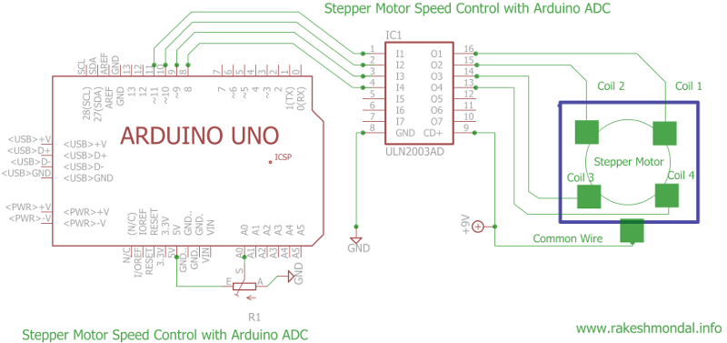
I used Eagle schematics layout designer for the schematics.You can use any other PCB designer as well such as PCB WEB.
PS: You can get a library for Arduino boards from E14 for Eagle layout designer.
Source Code:
/*
* File: Stepper Motor Speed Control using ADC - Arduino
* Author: ron / Rakesh Mondal
* December 20, 2013, 4:21 AM
** www.rakeshmondal.info
*/
int readADC = A0; //input pin for the potentiometer
int onbrdLED = 13, l1 = 8, l2 = 9, l3 = 10 , l4 = 11;
int Spd; // Variable to set the delay accoding to ADC val
int sometempvariable = 0; // Some temp var for adc val
void setup()
{
Serial.begin(9600);
DDRB = B001111; // Setting ddrb register to set pin 8 to 11 as output
}
void loop()
{
sometempvariable = analogRead(readADC);
if (sometempvariable <= 85 ) { Spd =8; }
else if (sometempvariable <= 170) { Spd = 10; }
else if (sometempvariable <= 255) { Spd = 12; }
else if (sometempvariable <= 340) { Spd = 15; }
else if (sometempvariable <= 425) { Spd = 17; }
else if (sometempvariable <= 510) { Spd = 20; }
else if (sometempvariable <= 595) { Spd = 23; }
else if (sometempvariable <= 680) { Spd = 27; }
else if (sometempvariable <= 765) { Spd = 31; }
else if (sometempvariable <= 850) { Spd = 40; }
else if (sometempvariable <= 935) { Spd = 45; }
else { Spd = 60; }
Serial.println(Spd); // print ADC value of analog reading
//--------------------
digitalWrite(onbrdLED, HIGH);
digitalWrite(l1, HIGH); digitalWrite(l2, HIGH); digitalWrite(l3, LOW); digitalWrite(l4, LOW);
delay(Spd);
digitalWrite(onbrdLED, LOW);
digitalWrite(l1, LOW); digitalWrite(l2, HIGH); digitalWrite(l3, HIGH); digitalWrite(l4, LOW);
delay(Spd);
digitalWrite(onbrdLED, HIGH);
digitalWrite(l1, LOW); digitalWrite(l2, LOW); digitalWrite(l3, HIGH); digitalWrite(l4, HIGH);
delay(Spd);
digitalWrite(onbrdLED, LOW);
digitalWrite(l1, HIGH); digitalWrite(l2, LOW); digitalWrite(l3, LOW); digitalWrite(l4, HIGH);
delay(Spd);
//---------------------
}
/* THE END */
Download the Project Arduino Stepper
The source code here is pretty much self-explanatory, no default Arduino stepper motor library is used here. We are literally setting the pins high or low for generating the pulses which would run the stepper motor. These pulses are then amplified with a ULN2003 in order to run the M35SP stepper motor. The on-board pin 8,9,10 and 11 are set to output. By default Arduino has pin 13 interfaced to a tiny onboard led which is configured in the code above to blink if everything goes right. An additional line of code to display the value of the current delay in serial monitor is also included , which would display the current delay in which the stepper motor is running ( in Milliseconds ).
Arduino Uno board uses a 8 bit microcontroller and the ADC is 10 Bit ADC, hence the resolution of the output of the ADC would range from 0 – 1023 ( this is general rule no matter which microcontroller you use). If we directly feed this value ranging from 0-1023 as delay in-between each step then , at the lowest possible range ( 0 milliseconds ) the stepper motor would not run at all. There is a limit to which these motors can endure, in my case this rusty 5 yrs.’ old stepper motor cannot respond to a delay lesser than 7 milliseconds, so the minimum possible delay between each steps has to be 8ms or more. On the contrary at the maximum resolution of the ADC which is 1023, the delay between the steps would approximately 1.02 seconds ( 1000ms = 1 second ) resulting the motor to rotate dead slow as it would need approximately 48+ seconds to complete on revolution. Hence the code has been tuned with few simple IF ELSE statements to make sure the motor runs at a minimum of 8ms at lowest possible ADC resolution and maximum of 60ms delay at highest possible resolution of ADC.

The last step
Wire up the components according to the schematics , upload the code , open the serial monitor, tune up and down the potentiometer .Enjoy.
PS: If you have a M35SP -8 stepper motor and it can run at delays below 7ms then please email me, I would be delighted to know. Thanks in advance.
Download the Project Arduino Stepper
VIDEO: Stepper Motor Speed Control with ADC
Also See: USB Stepper Motor Driver | Drive Stepper Motor with PIC18F
Thanks for Reading
Ron