PIC18F4550 ADC Stepper Motor Speed Controller

PIC18F4550 Stepper Motor Speed Controller
This tutorial deals with controlling the speed of stepper Motor using a pic18f4550 Microcontroller with a potentiometer. In my previous project we have tried the same with Arduino but the stepper motor couldn’t endure the delay below 35 milliseconds in-between each Steps. This project is one of the many applications of Analog to Digital Converter (ADC).
The inbuilt ADC module of pic18f4550 is 10 bit, and will be used for sampling the analog input into digital output. The Configuration of ADC used in this project is best suited for room temperature, or else time taken to charge (Chold) the capacitor inside the ADC module of PIC18F4550 would go high, else known as acquisition time. The reference voltage Vref for the analog input channel would be 0v-5v. Due to the inaccuracy of the internal clocks of the PIC18F4550, we will use external oscillator (20MHZ) to clock the ADC module of this microcontroller.
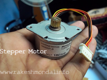
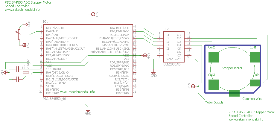
Stepper Motor used in in this project is an M35SP unipolar stepper Motor with step angle of 7.8. A ULN2003 (NPN Darlington transistor) chip would be used for amplifying the microcontroller output pules to match up with the operational voltage of the Stepper Motor. To feed the analog input to the microcontroller we will use a 10K Potentiometer which would be rigged to AN0/RA0 Pin of the pic18F4550.
This Project takes a maximum of 45 minutes to complete and stepper Motor itself is probably the most expensive component in this complete setup. If you wish to know in details about ADC or other stepper motor tutorials then you can refer my previous posts.
| Requirements | Specifications | Notes |
|---|---|---|
| Stepper Motor | M35SP -8 | 5 wire Unipolar, Step Angle 7.5 |
| Microcontroller | PIC18F4550 | PIC18F |
| Potentiometer | 10K | - |
| Compiler | XC8 - Lite | Link |
| IDE | MPLAB X | Link |
| Programmer | Pickit2 | Or any PIC programmer |
| Breadboard | - | - |
| Wire | - | - |
ADC Configuration for PIC18F4550:
| Configuration | Settings | Notes |
|---|---|---|
| Reference Voltage | 0 - 5 V | - |
| ADRES Register | Right Justified | 10 Bit ADC of PIC18F4550 |
| TAD | 2TAD | - |
| Clock Source | External | 20MHZ Crystal |
| Prescaler | 1/32 | 1/16 will be too close, hence 1/32 is good |
| Channel | AN01 |
Stepper Motor Wiring
If M35SP stepper Motor is used for your project then follow the wiring references and wire color codes given in the images below. If you wish to use any other stepper motor then you have to follow wiring labels and color codes of that respective stepper motor.

Schematic:
Source Code
IDE: MPLABX IDE
Compiler: XC8 Compiler (v1.34)
A compiled version of HEX file, project files along and separate source code is given below. The Stepper Motor is configured on to work on port B (RB7 to RB 4), and it is coded to work on Single Step wave mode. However the source code can be easily modified to work on Half step and Full Step sequence by changing the output pins order pins with LATB register.

Thanks for reading
Rakesh Mondal